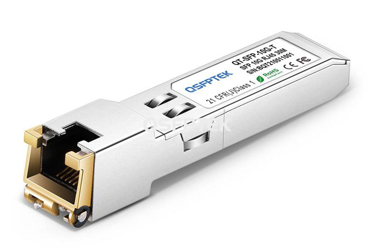
10GBASE-T Ethernet and 10GBASE-T Model Introduction: Development of 10G Ethernet
With the explosive growth of IP-based data traffic and the rapid development of streaming media such as mobile video and online audio and video, people have put forward new challenges to the information exchange capability of network communication, which has prompted the continuous advancement of Ethernet technology. develop. Since 1983, the first-generation Ethernet protocol standard 802.3 using Carrier Sense Multiple Access Technology with Collision Detection (CSMA/CD) has been released.
Ethernet technology has reached its thirtieth year: its transmission mode has changed from the half-duplex mode in a shared transmission medium bus-based architecture to a full-duplex mode using a switch-star topology architecture. The transmission speed experienced the first generation of 10Mbit/s, and later Fast Ethernet (100M), Gigabit Ethernet (1000M), and 10 Gigabit Ethernet (10GE), and the transmission rate increased by 10 times each generation.
In June 2002, IEEE released the first 10G Ethernet standard 802.3ae based on optical fiber transmission, and its transmission distance is between 300m and 40km. The earth has expanded the use of Ethernet technology: In November 2002, two organizations were established to study the transmission of 10Gbit/s data on copper cables: one is 10GBASE-CX4 to study the realization of 10Gbit/s on 4 pairs of coaxial copper cables.
The other is 10GBASE-T research to realize 10GbitJs on cat5e and cat6 twisted pairs.
In January 2004, IEEE passed the standard for transmitting 10Gbit/s on coaxial copper cable – IEEE 802.3ak, the transmission maximum The distance is 15m, which is suitable for the connection of the server backplane in the data center; in June 2006, the 10Gbit/s standard based on 4 pairs of unshielded twisted pair transmission – IEEE802.3an was officially adopted, with a transmission distance of 100m, suitable for network Backbone network and data center 1 In 2007, the optical fiber transmission 40G/100G Ethernet working group was established.
In June 2010, the new generation of Ethernet technology 802.3bg 40G/100G standardization was completed. 2. Established multi-mode fiber and symmetrical Physical layer communication specifications for copper cabling, but the standard makes no recommendations for UTP/STP copper cabling.
10GBASE-T Ethernet Model
The layered model of Ethernet corresponds to the bottom two layers of the OSI7 reference model, the physical layer and the data link layer. As shown below. In 10G Ethernet, the MAC sublayer and the LLC sublayer are equivalent to the second layer of the OSI 7-layer hierarchical model – the data link layer.
The LLC sublayer serves the upper layer and is responsible for segmenting and reassembling the data packets transmitted by the upper layer and encapsulating them into the Ethernet frame structure, and is responsible for the establishment and maintenance of the communication link, as well as the coordination between the arrangement, transmission, and reception of data deal with. The MAC sublayer is located between the LLC layer and the PHY, which shields the differences between different physical media and provides the LLC with a unified data format and interface.
OSI 7 Layer Model vs 10GBASE-T Layer Model
As mentioned earlier, 10GBE inherits the IEEE802.3 Ethernet frame structure, the maximum and minimum frame lengths, and the control protocol of the MAC layer. Therefore, compared with 1000M Ethernet, its data link layer standards have not changed much, but the changes are more obvious. is the physical layer.
The physical layer of 10GBE is divided into RS (coordination sublayer) PCS (physical coding sublayer) PMA (physical medium access) AN (negotiation sublayer) and other sublayers: RS is mainly responsible for mapping the data on the XGMII path to MAC/PLS Above the interface, at the same time RS and XGMII can connect the MAC to different types of physical media.
The PCS sublayer is between XGMII and PMA. It mainly completes the encoding of the data stream from the MAC layer and realizes the decoding of the data of the PMA layer. The PMA provides the connection information from the PCS service interface to the balanced cable physical medium connected by the MDI interface.
The AN sublayer is responsible for detecting the transmission capability of the medium or cable between the links, and selecting the optimal transmission technology that matches each other between the receivers. For example, 10M/100M/1000M or 10G, the addition of this sub-layer makes 10GBASE-T have good backward compatibility, which can ensure smooth network upgrade for users without loss of MDI (media-related interface), which defines the unified connection standard for the physical properties of the media interface.


